
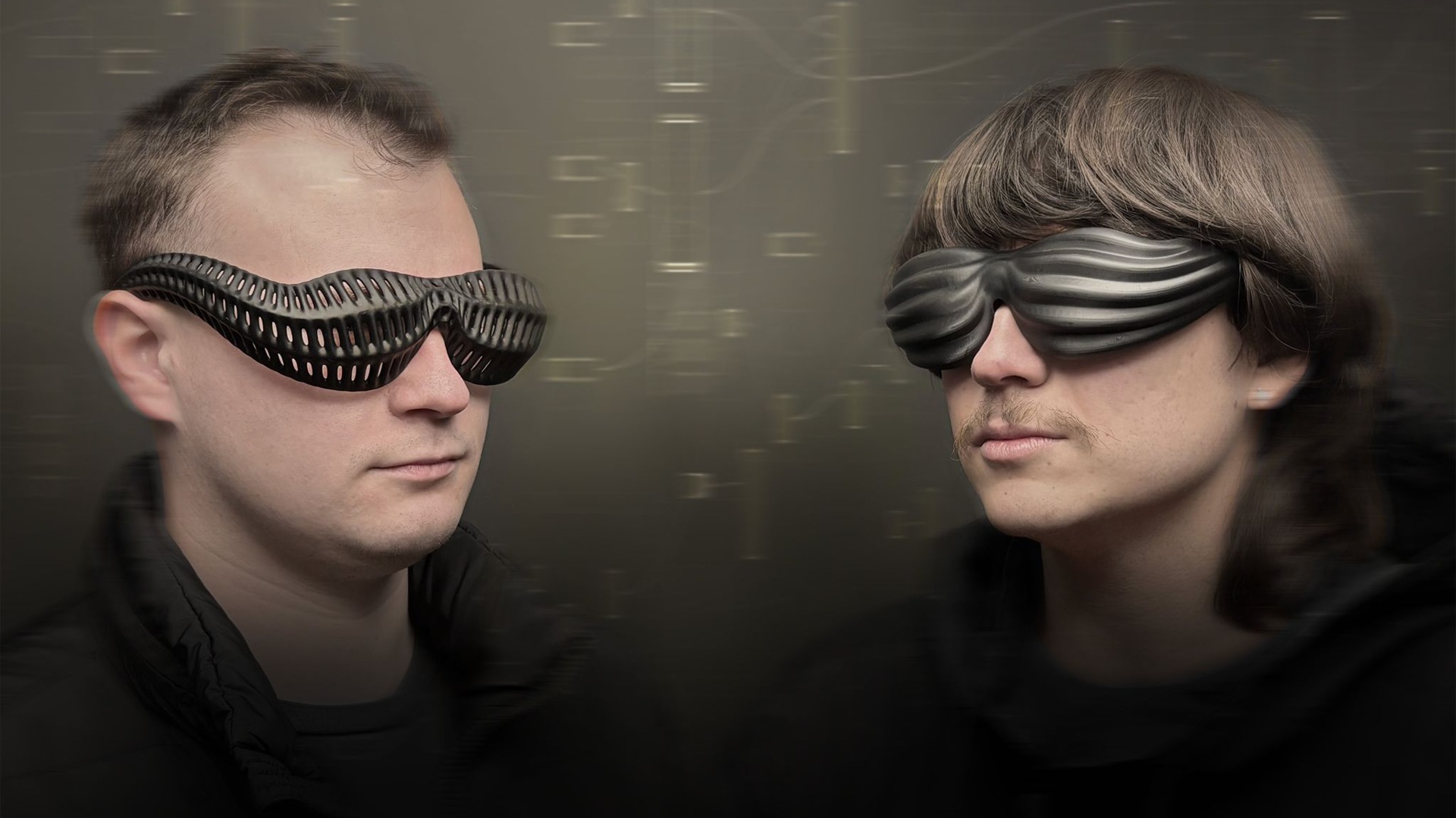
Advanced Textures in Carbon DLS™
Additive manufacturing presents opportunities to integrate texture directly into parts, including across curved surfaces and geometries that are difficult or impossible to mold. Digital texturing can produce detailed low-angle patterns, undercuts, and other complex features without costly mold etching or labor-intensive post-processing.
Because textures can be printed during product development, teams can evaluate surface finish, aesthetics, and performance before committing to final production tooling. This makes it easier to refine designs earlier while reducing the risk, cost, and delay of retooling later.
At Sherpa Design, we have three main methods for applying textures to additively manufactured parts utilizing Carbon DLS Printers: Carbon Design Pro, Siemens NX with Abode Creative Suite, and Node based texturing. These methods offer a range of cost, time, and complexity.
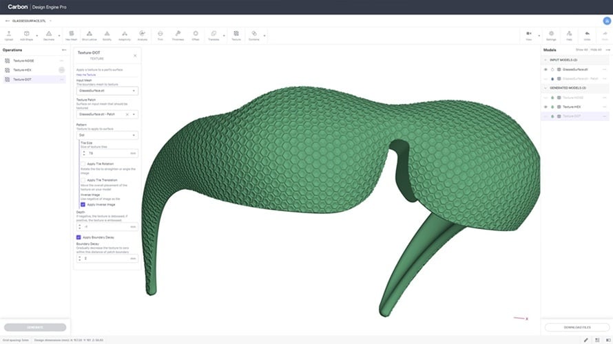
Carbon Design Engine Pro
Our first method leverages Carbon Design Engine Pro, our fastest and most cost-effective option. Using a sunglasses form as an example, we selected a faceted region by tangency, chose a pattern, adjusted the parameters, and generated the texture. All in under two minutes. This speed enables us to iterate quickly and move seamlessly from design to manufacturing.
Siemens NX with Adobe Creative Suite
Our second method offers further customization and more control. This workflow has two stages: bump map creation and 3D texture generation.
A custom bump map is designed in Adobe Illustrator and/or Photoshop. It is essential that the bump map covers the entire surface or tiles seamlessly.
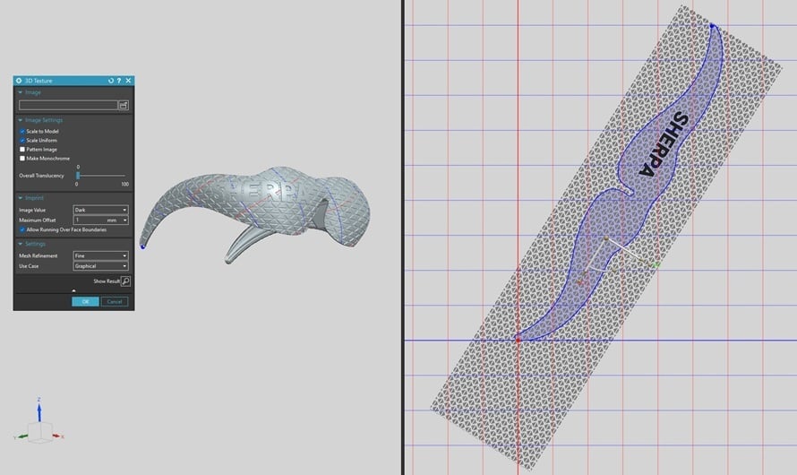
In Siemens NX, the bump map is applied to selected B-rep surfaces to generate a true 3D texture. The tool provides a range of tunable parameters, including monochrome toggling, offset distance, and mesh resolution. This presents the opportunity for unique aesthetics and integrated branding.
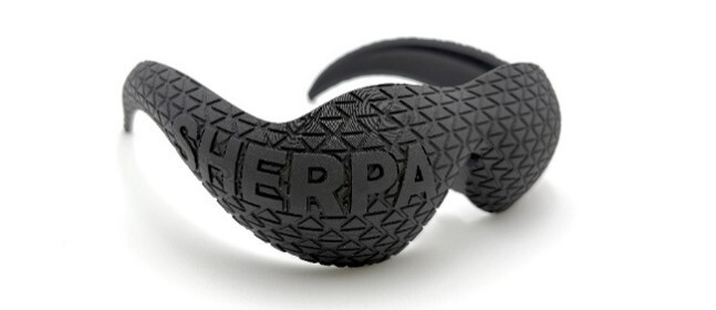
Node Based Texturing / Grasshopper Texturing
Our third method provides an unmatched level of dimension compared to bump map-based textures. We have two standardized workflows for designing these textures. However, the possibilities are endless.
Standardized Workflows
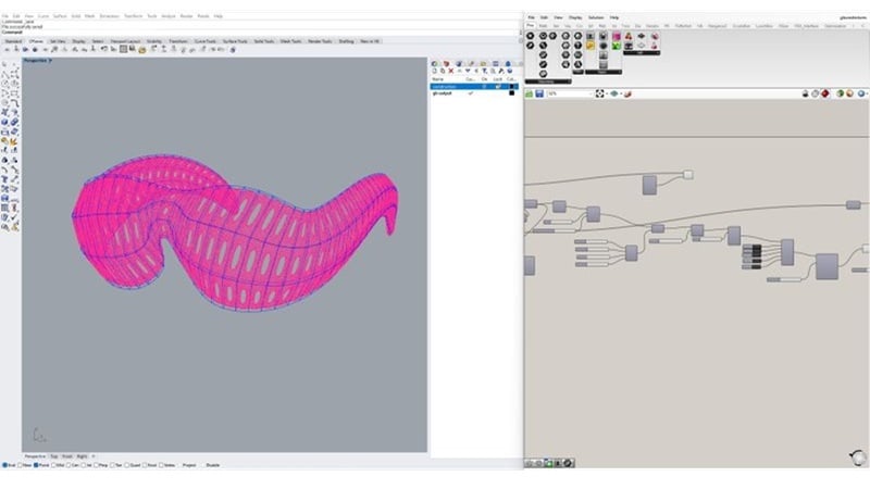
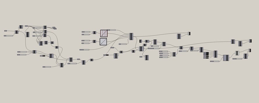
The first workflow divides or extracts UV data from B-rep surfaces. The surfaces are rebuilt or paneled using native tools and a variety of plugins (Weaverbird, Parakeet), pulling the edges from the B-rep as construction guides for surfacing.
The second workflow divides B-rep surfaces into meshes. Plugins give us a variety of meshing options. First, geometry is morphed to the mesh faces, and then Weaverbird is used to subdivide exterior faces. These textures can be further manipulated by additional data, with inputs for offsetting surfaces, and smoothing. Finally, patterns from the Parakeet plugin allow us to create exotic, alien textures on parts.
Texture Selection Tricks
There are tricks to take control the selection of texture regions with both methods.
One trick is use a CAD program like NX, which can select regions by surface edges. The texture is manually placed and tiled over the UV map. It is helpful to take a screenshot of the UV map to use as a guide while designing the bump maps. The meshing resolution can be adjusted by the user resulting in better resolution of textures; however, processing times can be long. There are benefits to this approach. There is one less file transfer between different CAD packages. It also uses a more traditional feature tree interface rather than one with a series of linked components like Grasshopper.
Another trick to control texture selection is to use Carbon Design Engine which selects regions by angles between facets. It spreads over smooth transitions unless a feature is added to break the tangency. The resolution of the mesh can not be determined by the user, and occasionally produces textures with coarse faceting. Applying textures in Carbon Design Engine is very fast, and it's a great option for quickly ideating part textures, but lacks some of the control and customization of other methods.
Conclusion
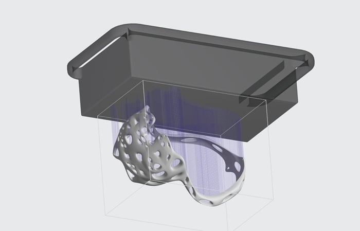
Additive manufacturing makes texture a practical design variable rather than a late-stage finishing decision. By selecting the right workflow, teams can balance cost, development time, control, and complexity for each application. More importantly, these methods allow texture, branding, grip, and other functional or aesthetic surface features to be evaluated and refined earlier, helping teams move toward production with greater confidence.
